With our choice of 8020 for the interior, using "half-size" 8020 as the interface to attach the structure to the wall is a natural choice. This is one method covered in this Ourkaravan video, the other method being directly bolting the 8020 structure to the wall. To borrow from software development, using an interface like the "half-size" 8020 allows you to "separate the concerns" of the van walls and the structure. Meaning, the 8020 structure can attach to the interface where ever it needs to and the van wall can attach to the interface where ever it needs to. Thus, the structure and the wall don't need to be concerned with each other. This approach is also similar to how we used L-track on Van 1.0 to attach our bed and cabinets.
The only downside, is you give up 0.75 inches on each side of the structure to account for the "half-size" 8020. This is not actually a big deal (for us) because it spaces our structure out from the van walls such that the slight inward curvature of the walls doesn't interfere with our structure.
So, given all that: All 8020 structures are secured to the walls via 1575 series 8020 that is directly fastened to the walls running fore-aft on both sides of the van. Method of attachment of the 8020 structure to the 1575 series is via 8020 gussets.
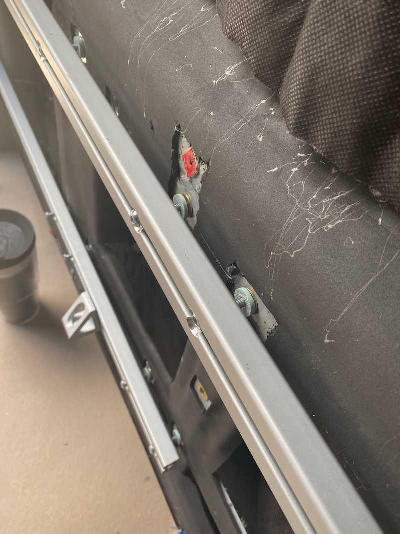
1575 series is fastened into existing factory holes fitted with 1/4-20 plus-nuts using 1/4 inch button-head socket capscrews. Based on the stackup of the 80/20, and the two spacers, a 1.5" fastener have full thread engagement in the plus-nut. These fasteners are available from McMaster.
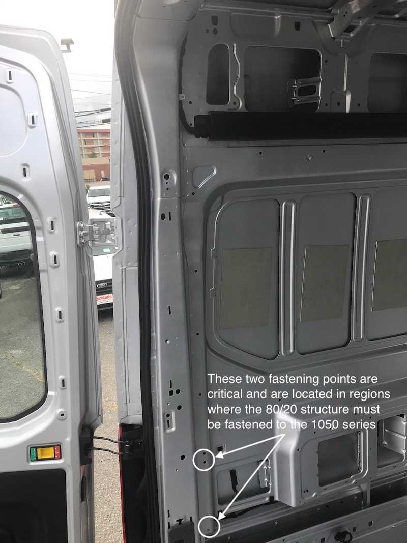
It is important that the fastening method is flush or recessed with respect to the outer surface of the 1575 series. This is because there are some limiting regions at the ends of the 1575 runs were 80/20 structure needs to be fastened to the 1575 series directly over or adjacent to where the 1575 is through-bolted. An example of this region is shown below.
 After this picture was marked up we shifted to 1575, so ignore the reference to 10 series.
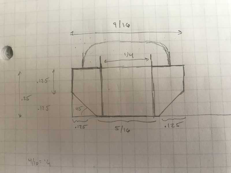
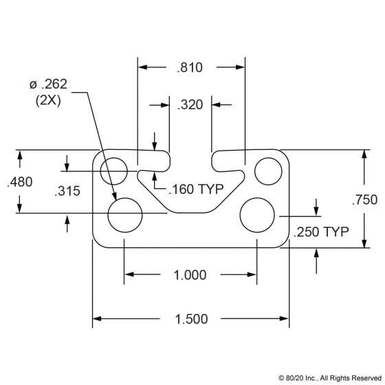
Based on the dimensions of the 1575 series, a 1/4-20 sized button-head socket capscrew would not rest flat and allow for a proper pre-loaded joint without putting a bending stress on the head. To avoid this problem, a slide-in insert that matches the profile will be used. The insert will be fabricated from FR-4. Based on the max head height of a 1/4-20 button-head socket capscrew (0.132 in) the thickness of FR-4 to ensure the head does not protrude is 0.3480 in. Based on this, 1/4 inch thick FR-4 will be used, which is available from McMaster in sheet form. The FR-4 sheet will be cut into 9/16 inch widths, chamfered with a 45 degree router bit, and drilled.
 Pretty straight forward to fabricate with a band saw, drill press, and table router.
The top of the 1575 series will need to be opened to pass the pan head. Ourkaravan demonstrates doing this easily with a step bit.
To provide a thermal break, 1/8 inch FR4 will be used between the backside of the 1575 series and the wall at the fastened locations. This spacer is factored into In the overall arrangement model.


