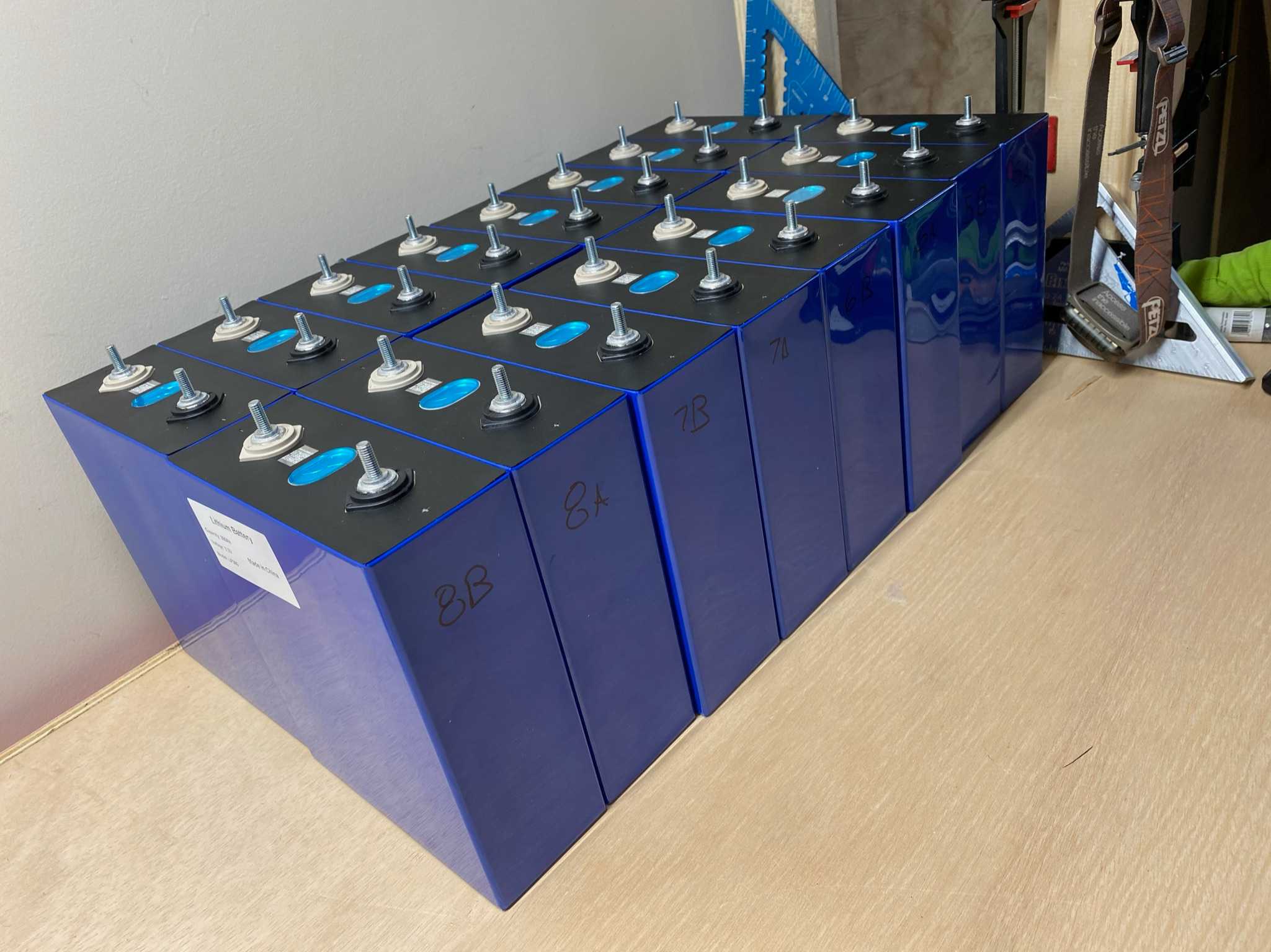
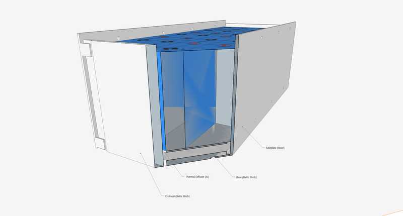
The battery will be constructed of 16 280AH cells in a 2P8S 560AH 24V configuration. It will be installed behind the driver side rear wheel. It is installed between the wheelwells. The selected design concept is illustrated below.
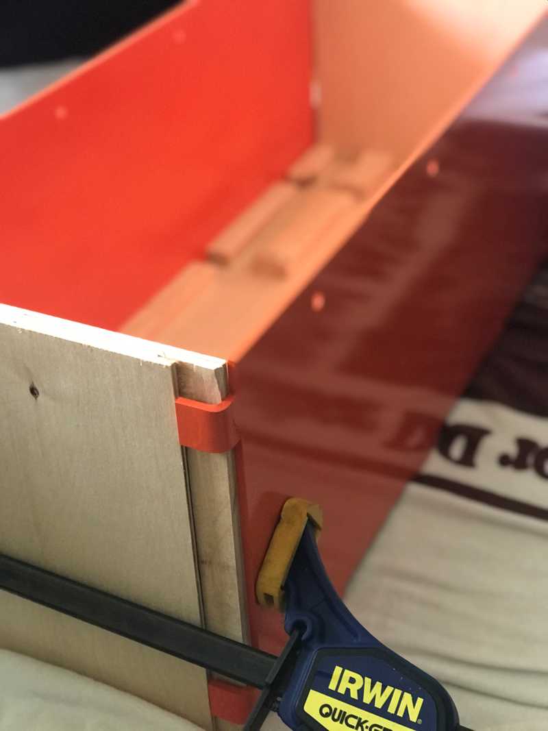
The design consists of two 3/16 steel side plates that sandwich the cells and are fastened together with 1/4-20 high strength steel all-thread and nyloc nuts. The side plates include tabs that capture a plywood-aluminum base plate and plywood end plates to fully secure and constrain the cells. The baseplate includes channels for installation of heating provisions and a 1/8 inch aluminum thermal diffuser in direct contact with the cells. The plywood endplates will allow for attachment of battery management system components.
Upon soliciting for fabrication, I found it was cheaper (and easier) to go with sendcutsend.com using a bent tab design. The new design is here. To accomplish this, the design was reworked with the tabs the same thickness as the material and minor geometry changes to accommodate the bend allowances. The critical dimensions (interior tab-to-tab distance, top plate edge-to-interior tab distance, hole spacing relative to center and top edge), remain essentially unchanged. The aluminum baseplate/thermal diffuser was also ordered from sendcutsend. The design is here.
Cell Electrical Insulation
According to the Will Prowes' forum, the aluminum cased cells have positive terminal voltage on the outer case. This means each group of cells will need to be isolated from each other and from any structure. This was accomplished by Kapton tape.
Cell Compression
EVE engineers recommend approximately 12 PSI, with no more than 17 PSI, to be maintained on the cells. Allegedly this increases rated cycles from 2500 to 3500. They also identify approximately 1 mm expansion between 0 and 100% SOC. Use of springs and belleville washers were evaluated to provide compression. In the selected design, the flex of the side plates themselves function as two springs in series with any other springs in the system. By designing the plates appropriately, they can be relied on exclusively for compression at high SOC and to accommodate the expected growth. To apply some compression at low SOC, single bellville washers, fully flattened, will be used. While this method will not be as calibrated as the others, it can ensure some compression above 0 and less than 12 PSI at full SOC and is more compact, simpler, and cheaper. This belleville washer fully flattened will give about 2.5 PSI at 0% SOC for this design. To apply some compression at low SOC, springs, compressed solid, are used. This method ensures some compression above 0 and less than 12 PSI at full SOC. The LHL 625B 01 from Lee Spring is used which provides 3.8 psi when compressed solid.
For top balance, prior to final assembly, the stack of all 16 cells was compressed by two 3/4 inch plywood panels with held with 4 rods all 1/4-20 all-thread. The compression provided by the plywood panels was provided by 4 springs outboard of the panel on a single side. The four springs were type LHL 750B 08 from leespring.com which provided 13.2 to 10.3 PSI with acceptable room for cell expansion.
Cell Interconnection
Parallel cell connection will use either CALB-style flexible copper busbars, solid busbars from the supplier, or custom copper busbars. Parallel cell connections use custom busbars with a bent arch to accommodate cell swelling without imposing high stress on the cell terminals.
Series cell connection will use solid busbars, either custom or purchased. Series cell connections use custom flat busbars. Significant growth is not anticipted in this dimension. The bars are slightly slotted. This will not affect current flow area since they stack on top of the parallel connections.
All busbars were cut by sendcutsend.com.
Nickel plating will be considered. Bus bars are nickel plated.
Battery Heating
Channels between the plywood base and aluminum baseplate/thermal diffuser house infrared LED strip lights. Two redundant sets are installed with one functioning as an installed spare. There are also heating mats installed on the outside of the steel side plates. The total heat output when energized at 24 volts is about 30 watts which should be plenty sufficient, with insulation, to keep the battery above freezing even if the van internal ambient temperature is below freezing.
Regarding Updates
This article was updated to reflect the final design and implementation. We apologize for any mixed verb tense. It was written and then updated months or years later. Where we felt posterity was of value, we chose to use strike-through on sections that are no longer accurate. We have generally maintained the date of the article to be the original.


